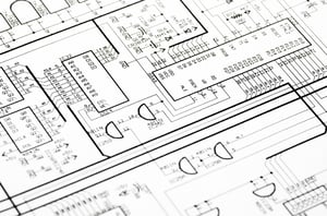
 Every piece of industrial automation will have schematics (we hope!) These drawings communicate design intent from the engineer to the assembler, troubleshooter and person doing maintenance. With pages showing power distribution, input/output (I/O), and safety circuits, a well-organized print set can be invaluable for the life of the equipment. Knowing how important these are, it’s surprising how few resources are available for a professional to learn how to create schematics.
In my experience, most of industry draws schematics with AutoCAD LT from Autodesk. I learned to use AutoCAD in college drawing 2D representations of mechanical parts. I wasn’t well prepared for electrical schematics in industrial automation when I entered the workforce. Architectural courses are on the internet, but learning to draw toilets and countertops doesn’t really close the gap. After years of trial and error, reading and modifying other people’s drawings, and mentorship, I finally developed a process and skillset to produce schematics cleanly, efficiently, and with an eye towards the future. For those seeking to improve their skillset, consider five tips to learn with less frustration.
1. Keep automation design simple
The first rule is to keep it simple. A lot of details could be included in a schematic – for example: every wire color, gauge, rating – but if the detail isn’t necessary, it’s just visual clutter. It’s important for a technician to be able to quickly understand the machine by paging through these drawings, and more detail makes it harder to understand at a glance. Sometimes a detail like wire color is helpful in the schematics, and gauge is better left for a pull sheet. Sometimes wire color can be safely assumed, as with blue and white/blue for 24 V dc and 0 V dc, respectively. Depending on context, those details can be omitted.
 2. Leave space in automation design drawings
I often see drawings with every page chock full of devices and wires, and page numbers laid out consecutively with no empty pages left. This is harder to read because of the density; it also leaves no room for future changes. These schematic drawings need to support the machine for its whole life – easily 20-30 years where the control system is concerned, and well beyond if the control system gets updated. If a page looks like it’s going to get crowded with devices, spread those devices over more pages. And leave unused page numbers for each section of the schematic – power distribution, input/output (I/O) information, drives, etc. Someone may need to add an I/O module and a drive in the future.
3. Provide enough realism in automation designs
Prints should not be photo realistic representations of the part we’re drawing, but adding detail to components helps them be quickly identified. For example, a schematic representation of a servo drive may start with a rough drawing of how the drive actually looks followed by adding terminals for the sake of the schematics. Many times, a dwg/dxf file can be downloaded from the manufacturer’s website to provide a good starting point. If you decide to use these drawings, it’s good practice to simplify by deleting unnecessary details/extra lines and colors. Don’t forget the first rule when applying this one. Keep it simple.
4. Reusable blocks of automation design
AutoCAD supports reusing chunks of drawings with what they call “blocks.” The architects use these to add toilets to their drawings without having to draw the toilet every time. We use blocks to add things like proximity switches, PLCs, drives, and panel components. Almost every device in my drawings is a block. This saves considerable time and brings a level of uniformity to the drawings. Blocks can be purchased for this type of drawing, but it’s better to make your own so they all feel like they belong together. If your company has existing drawings or blocks, use those as a starting point.
5. Use a template for automation design
It’s hard to start with a blank page. After you’ve gone through the effort of making a drawing set, save it for future use as a template. It doesn’t have to be a special template file. Just keep one of each type of drawing in a folder somewhere and copy that whole folder when starting a new project. Doing so fills in the title sheet, power distribution, IO, drives, etc., saving time. Just adjust the information to the new design. It’s good practice to delete any customer-specific information before saving the template set to avoid any chance of information accidentally going to a different system integration or automated machine design customer.
To learn more about Radwell

For a behind-the-scenes look at Radwell

View the original article and related content on Control Engineering
https://www.controleng.com/articles/five-tips-for-effectively-drawing-electrical-schematics/
https://stream.cfetechnology.com/contentstream/tracking/?fdid=9974&uid=505771&cp=36&pub=45